A couple of months ago, I made a pilgrimage to the nearest Micro Center, with no other purpose than to do what men accuse women of… retail therapy. No set purpose or need, just wander around and see what is new. In the 3D printer department, I found a bin of open box discounted items – including an MKS 1.2 controller for a 3D printer, for cheap. really cheap. Hmm…. <thinking>. I wandered over to the section with the new printers. SLA – fancy, cheap, fumes way worse than ABS. pass. Then I look at the FDM machines, and I noticed they all have the same parts and construction as my daVinci 1.0. Sure, maybe a better extruder, definitely a modern controller. Only thing missing from mine is the modern controller… for $16, just around the corner…
And thus started my adventure.
The da Vinci 1.0a was released in 2014, and happened to land under the Christmas Tree the same year. I was happy as a clam. Then I started discovering its weaknesses. Filament was 2x more expensive than for other machines. Fixed that! Within the first couple of years, even the plastic build plate support melted into a pile of slag. Replaced that with a piece of cement board, as the plastic build plate support had melted into useless slag, when exposed to the build plate temps. Hey! no laughing!! it worked!
Eventually I got frustrated with the quality of the XYZ software and its constant need to phone home. Most prints were very weak between layers and would delaminate at the slightest excuse. Upgrading to Repetier fixed those problems, but still was not able to print tall and thin, or just thin. Thin walls would sag, and tall thin could not cool down fast enough and would be a mess – even when running ABS at 220C. PLA would just not work at all. Arrgh!
The summer before Covid hit, a friend suggested I take a look at Octoprint. Loved that one.
After all those upgrades, print quality was significantly improved. Could I do better? Could the latest version of Marlin make a difference? No idea, but installing more modern firmware on the existing hardware was not an option – Repetier for daVinci has not been meaningfully updated in 7 years. Proper Repetier does not look to have received significant updates for about 3 years.
As it turned out, upgrading the da Vinci to the MKS board was non-trivial, and I made a few mistakes. Some of the issues:
- Pinouts are incompatible
- the da Vinci uses 2mm pitch connectors, the MKS board uses 2.54mm pitch connectors.
- The MKS board does not support the optical endstops by default.
- For most of the connections, all wires are the same color – which is ground, pos, signal??
- Where the cable was color coded (to the extruder) I could not find any pinout documentation
- How many steps per mm for each axis?
- Some da Vinci hw features are not standard by default
- filament counter (no Marlin support)
- Filament sensor… where, o where, do I connect thee??
- case lighting dimmer – 12v output
- door open sensors
- front panel??
Lots of roadblocks, but I made it through. Was it worth it? Below is a shot of the Benchy print benchmark. On the one hand, it looks like crap until you consider this is only the 4th or 5th print from the rebuilt machine. Cura has not been tuned. Also, this was printed at 0.1mm pitch – before the upgrade, this level of detail was not possible. With the previous controller, I could print this at .2mm pitch, but generally the wheel house from the windows up would be a mess.
Improvement=success, so definitely worth the effort. Worth noting, I am still running the original printhead.
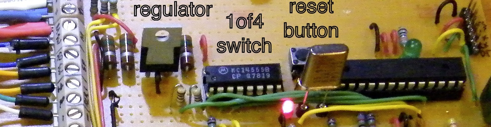
The Boring Technical Details
Below I document pinouts and their new connection points, as well as the Marlin config changes.
- Board – MKS Gen compatible
- Drivers – DRV8825 (32 micro steps vs 16 microsteps for A4988)
- Nema 17 stepper – 200 steps/rev
- with A4988 – 3200 steps/rev
- with DRV8825 – 6400 steps/rev
- Marlin – latest from github
- Front Controller – Smart Display Controller Ramps 1.4 2004LCD
Extruder AUX Pinout
- Red – Filament Sensor – Board D1 (AUX 1)
- Red!! – filament counter – NC
- orange – temp sensor GND – E0 header
- yellow – Fan Positive – FAN header
- green – Fan Neg – FAN header
- blue – NC
- black – temp sensor – E0 header
Optical Endstop Sensor
The endstop sensor needs a few extra resistors to work correctly. The MKS board provides 5v, however the da Vinci board provides 3.3v. A 220 ohm resistor is needed on the A pin to correct the voltage. The sensor requires a pull up on the C pin. This can be provided either with a 10k ohm resistor from the 5v source, or could be configured within Marlin to set the board sensor pin with a pullup. I chose the resistor route. Schematic below.

Unfortunately I ended up replacing two optical endstops with microswitches. It took me a few days to track down functional info on the optical endstops. Meanwhile I had been testing them (well, just the X axis) at 5V and getting no results. Even once I found proper config info, the X axis endstop failed to work. Giving up, I replaced the Y and Z axis with microswitches I had on hand. The X axis is harder to replace, as it is mounted on the carriage and space is limited. In the end, decided to replace the ‘failed’ optical endstop on the X axis with the cover switch I removed (same part). The spare switch worked on the bench, and failed when inserted in the system. Turns out, two of the three endstop wires had failed – no signal.
XYZ used 26 gauge PVC insulated wire with only a few strands of copper. The X axis gets the most flex and I had replaced a number of the wires before. This time replaced all of them, both the stepper and endstop with proper silicone test lead wire. Same gauge, but much more appropriate for the use.
LED Lighting Strip
The MKS board does not have an obvious option for driving the LED strip as designed. Pin1, the lower one in the image, is the pwm pin – requires 12v input. The middle pin is ground, and the top pin is +12v. Easiest solution is to join pins 1 and 3, and connect to the 12v header. This is the path I took.
An alternative is to drive the pwm pin via the E1 header, and make adjustments in Marlin, if you want to be able to turn the light on/off or dim it.
Connecting the front panel
Ordered a roll of 10 conductor ribbon cable and popped the end connectors off the provided cables. Ran the new controller cable via the same path as the original front panel cable. On the panel end, had to remove the strain relief caps from the cable ends to get it to fit in the available space.
The 4×20 LCD screen is the same height as the screen cutout in the da Vinci, but it is quite a bit longer. A bit of work with a Dremel and file extended the opening. Additional trimming was needed for the speaker, knob and reset button. In the Marlin config docs I changed the knob rotation order, setting clockwise to always be UP, and counter-clockwise to always be DOWN.
Power Supply
The MKS board is designed for 12V input (also 24V). The da Vinci power supply has outputs for 12v (3x), 5v and 3.3v. One of the 12v lines was connected to the board supply, and the other two to the heater input. The 3.3v supply is currently unused. I put a small header on the 5v supply to run the fan cooling the board and the Raspberry Pi running Octoprint.
If the bed heater and the extruder heater are running at the same time, the LED case lights will slightly flicker. The power supply is probably running at its limit for this machine. I considered upgrading, but in the end decided to leave it in place. It fits, and it was specced specifically for the machine’s power needs. It ain’t broke, so don’t fix it.
Octoprint
Unfortunately I forgot to mount the Raspberry Pi at the same time as I mounted the MKS board. All cables were affixed, bezels reinstalled to the machine, when I remembered the Pi. Must have been on a sugar high.
Initially tried to run the Pi from the 5v header on the MKS board. Unfortunately the header outputs 4.4v, and the Pi is not happy about that. Running the Pi from the dedicated 5v rail achieved the desired result. A short printer usb cable was found for connecting the MKS board and the Pi. The 2nd USB cable is for the camera mounted inside the machine.
The Pi sets its IP via DHCP. Octoprint is set to automatically connect to the printer control board and then displays the machine’s IP on the control panel. No need to guess the Octoprint IP address.
Steppers and print area
The da Vinci steppers do not all turn in the same direction to increase position from zero. This I discovered after I had replaced the board side 2mm pitch connectors with 2.54 pitch connectors. The fix was to reverse them in the config file. My direction settings will not match yours, if you are using this info to build your own. Fortunately nothing will break. A bit of calibration testing will immediately show something going in the wrong direction. Reversing direction in the config and recompiling will fix the problem
The da Vinci build area is 200x200x200. It is also designed with a ‘home’ location. To get the head to park in the correct spot, the home location is defined with negative numbers. The 0x0x0 location is with the bed fully raised and is the corner closest to the parking spot. Because of the microswitch on the Y axis, my home location is -35, -8. With an optical endstop on Y, the location will probably be -35, -15.
Stepper step counts per mm were a tough one. Online I found info on the Repetier configs for X and Y on the machine, and I doubled them to 160 steps/mm for X and Y. Z took a bit longer, as it required quite a bit of empirical testing and reading. 5150 steps/mm is what I discovered. Did not make sense until I did the math. The Z axis drives a lead screw directly. One full stepper rotation with the DRV8825 driver is 6400 steps. 1mm is about 3/4 rotation.
Marlin supports mapping the build surface and adapting the print job to match the surface elevations. With 5150 steps to work with, this machine has all the fine Z control any of my projects could ever need. If I bother to enable that functionality.
Testing the filament feed was one of the easiest to do. With a pair of snips I marked about 50cm of filament in 1cm increments. Using the front panel controls, I would feed filament in 1cm increments to measure the error. If 10cm of filament had a 5mm error, I would recalibrate the config, upload and test again.
Temperature sensors
The two temperature sensors in the da Vinci are not identical. Testing them was fairly easy. From a serial console via USB, I queried the temperature outputs. The extruder came back as 25C (room temp), but the bed temp was totally in left field. After a bit of googling, it became clear that almost all temperature sensors are calibrated at 25C. Ha! I got that! room temp! Pull out the trusty VOM, measure the bed sensor ohms ~ 400k. Once the bed resistance was set in Marlin, the serial monitor reported the same temp for the extruder and bed (mostly)
I did not bother to calibrate either sensor at higher temps and get them exact. It is not really necessary. Consistency is needed from reading to reading, but if it is consistently off by 3.1415%, who cares. Have a piece of pie, adjust your slicer settings for a higher or lower temp based on observed results and print. Just as a note… the readings are consistent with a variability of about +- 0.75C. When heating filament at 230C, that small variability will make no difference.
Marlin configuration
Quite a bit of time was spent calibrating the steppers, identifying and testing input pins and calibrating temperature sensors. Although the MKS board is Arduino Mega based, before each upload it needed to be updated with the Arduino bootloader.
Merlin configuration.h changes
#define MOTHERBOARD BOARD_MKS_BASE
#define CUSTOM_MACHINE_NAME "DaVinci MKS"
#define TEMP_SENSOR_BED 1000
#define X_DRIVER_TYPE  DRV8825
#define Y_DRIVER_TYPE  DRV8825
#define Z_DRIVER_TYPE  DRV8825
#define E0_DRIVER_TYPE DRV8825
#define DEFAULT_AXIS_STEPS_PER_UNIT   { 160, 160, 5150, 220 }
#define Z_HOMING_HEIGHT  4
#define Z_AFTER_HOMING  10      // (mm) Height to move to after homing Z
#define X_MIN_POS -35
#define Y_MIN_POS -8  // This will be higher (-15?) if using optical endstop
#define FILAMENT_RUNOUT_SENSOR
#define FIL_RUNOUT_PIN 11
#define EEPROM_SETTINGS     // Persistent storage with M500 and M501
#define PREHEAT_2_LABEL       "ABS"
#define PREHEAT_2_TEMP_HOTEND 230
#define PREHEAT_2_TEMP_BED    90
#define PREHEAT_2_FAN_SPEED     127 // Value from 0 to 255
#define NOZZLE_PARK_FEATURE
#define NOZZLE_PARK_POINT { (X_MIN_POS ), (Y_MIN_POS), 190 }
#define SLIM_LCD_MENUS
#define REVERSE_ENCODER_DIRECTION
#define REVERSE_MENU_DIRECTION
#define INDIVIDUAL_AXIS_HOMING_MENU
#define SPEAKER
#define REPRAP_DISCOUNT_SMART_CONTROLLER


Set endstops
#define X_MIN_ENDSTOP_INVERTING false // set to false for davinci optical endstops
#define Y_MIN_ENDSTOP_INVERTING true //  May need to set to true for mechanical endstops
#define Z_MIN_ENDSTOP_INVERTING true // May need to set to true for mechanical endstops


inverting stepper direction - either reverse the cabling or change the below.
#define INVERT_X_DIR true
#define INVERT_Y_DIR false
#define INVERT_Z_DIR false


disable functions
//#define THERMAL_PROTECTION_CHAMBER // Enable thermal protection for the heated chamber
//#define THERMAL_PROTECTION_COOLER  // Enable thermal protection for the laser cooling
Merlin configuration_adv.h settings
#define BED_RESISTANCE_25C_OHMS      400000  // Resistance at 25C
#define WATCH_BED_TEMP_PERIOD        90 // Seconds
#define ADVANCED_PAUSE_FEATURE
#define HOST_ACTION_COMMANDS  //these functions needed for octoprint
#define HOST_PAUSE_M76
#define HOST_PROMPT_SUPPORT